|
 |
 |
 |
 |
 |
 |
 |
The
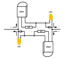
Simple Directional Lighting Circuit. This circuit is simple hence it is compact and easily installed into a diesel loco. There are other circuits which use diodes which select which light or LED turns on but these generally rob the motor of voltage. It is important to connect a ceramic capacitor across the motor to eliminate any HF noise generated by the loco’s motor. The LED will generally light up when the track voltage is 2 to 3 volts and will not rob the motor of any voltage hence the top speed of the loco will not be affected. The cost of the circuit is approximately $10. If the circuit was to be used in a loco with only driver’s cab then only half the circuit is required. This is what I have done in my 42class loco. |
| Flicker
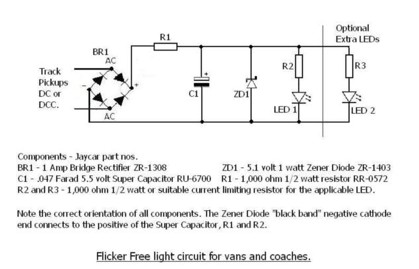
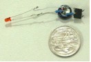
Free Lighting. The flicker free lighting circuit is ideal for lighting up rear tail lights of trains and also the headlight of steam engines. I have used one in the front of an Austrains 36class loco. The main advantages of this circuit are that the lights stay on when there is a disruption in the track power and also does not require batteries to achieve the effect. So when the train stops at a station the light remain on. The main component in the circuit is the 0.047F supercap which acts like a battery. The single LED in the front of my 36class loco remains on for approximately 2 minutes after power is removed. If I was to install more circuits into other locos the modification I would make is to reduce the value of R1 from 1KΩ to 560Ω. The reason for this is that the capacitor will charge faster hence the light will come on quicker. The main reason for the 1KΩ value of R1 is that this circuit was also designed for use on DCC layouts and the higher value would reduce total the inrush current when the layout is initially turned on with many of these circuits being present. This is not such an issue with DC layouts. When the circuit is used for illuminating the rear lights of a brake van a red LED and fibre optics would be used. I would also leave the value of R1 in this application as 1KΩ. |
  |
| Fibre Optics The fibre optics which are used for the lighting up of the lights of model trains are made from plastic and are quite large. The table below shows examples of the sizes available and their equivalent HO size. |
| Fibre Size | 0.5mm
|
0.75mm | 1.0mm | 1.5mm | 2.0mm |
| Equiv HO | 1.7”
|
2.6” | 3.4” | 5.1”
|
6.8” |
| Why use fibre optics? Fibre optics allow for prototypically correct sizes for lights which can not be achieved by only using LED’s or incandescent lights. Also through the use of fibres the appearance of multiple light sources from a single light. My applications of fibre Optics and Directional Lighting. The LED’s I have used in lighting up my locos are the Protypical White LED’s (or Golden Glow) as they give off a light similar to incandescent globes. The normal white LED’s which are commonly available from Dick Smiths and Jaycar have a slightly bluish colour to the light. I have used the first lighting circuit to light up two Powerline 81class locos and the flicker free light circuit in an Austrains 36class loco. |
  |
Fitting
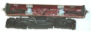
the fibre optics to the 81class loco. I have two Powerline 81class locos, one has been modified to have a Mains West chassis kit under it and the other has an L&C chassis kit. The Mains West chassis loco lends itself very easily to having all the lights working as the pilots are an integral part of the chassis where as the L&C chassis the pilots are attached to the chassis. On this loco I have lit up all the forward looking lights ie the headlights, the marker lights and the fog lights. The sizes of the fibres I have used are: • 0.75mm for the marker lights • 1.0mm for the fog lights • 1.5mm for the headlights.On the L&C chassis 81class loco the easiest approach I think would be to have one light source for the body mounted lights and another for the fog lights which are mounted on the pilots. Before installing the fibres some planning is required, this being: • The location of the LED for the light source. • How the fibres protrude through the loco body. Ie the size of the hole and the thickness of the body. • How is the LED and the ends of the fibres to be held in alignment. |
| LED /
Fibre alignment. The method I have used of holding the bundled ends of the fibres in alignment with the LED is a 4.8mm rivet. Why a rivet? Because it was the only piece of round tube I had…… The rivet being aluminium was easy to drill out to the correct size. The first step is to cut the flange off the end of the rivet. I cut off the flange in such a way so as to leave a square end on the rivet. This was useful to hold the rivet whilst it was being drilled out using a 3.5mm drill. The idea here is to insert the 3mm LED into one end and the fibres into the other. The rivet is glued to the inside of the roof of the loco approx 50mm from the end (this is not critical) but maybe 60mm could have been better. I used 5 minute Araldite to glue the rivet in place. Installing the fibres. Cut the fibres to length. For the fog light fibres allow sufficient length so that they will be routed in such a way that they don’t interfere with the bogie movement. Smooth the ends of each of the fibres using a jig so that the ends are square. The fibre is rubbed smooth on a piece of 600-1000 grade wet and dry paper. It is important that the ends of the fibre are square and flat so as to allow the most light through. The end of the fibre which will be protruding through the body should be heated carefully. The end of the fibre is heated by carefully bringing it into close proximity of a soldering iron. Don’t touch the two or over heat it. The heating of the fibre causes it to mushroom a little. There are two reasons for this. The first being the mushroom end will stop it being pulled through the model and secondly because the end grows slightly a smaller fibre size maybe used for the light. The marker lights require a small brass tube to be used as a guide for the fibres. The purpose of the tube is to fill the original hole and also keep the fibres in correct alignment. The size of the brass tube should be so that the 0.75mm fibre is a neat fit and also one end has to be turned down slightly so that it will fit the hole in the body. The guides are then glued in place prior to the fibre installation. As the marker lights are dimmer than the rest of the lights I have painted the ends of them with a white paint prior to be installed. Feed all the fibres through their respective holes and then into the front end of the rivet. The fibres are then held in place with Blu Tack. The Blu Tack is used to prevent light escaping out the end of the rivet and lighting up the inside of the loco. The fibres are also painted black as any imperfection in the fibre causes it to radiate light which also causes the light to glow inside the loco. The next step is to build the simple directional lighting circuit using so that one LED fits into one of the rivets and the other LED fits into the other rivet. If the lights turn on for the wrong direction transpose the connections between the motor and the lighting circuit. I have used electrical tape to hold the circuit to the roof of the loco. Another method for the aligning of the LED to the fibres is to drill small holes in the end of the LED and gluing each of the fibres into the LED. I don’t like this one. The advantages I believe for using a tube for the alignment of the fibres to the LED are: • The lengths of the fibre can be set and installed prior to the light circuit installation. • If there is a fault in the electronics then the lighting circuit can be easily removed. • Allows for easy separation of the chassis and body. • A smaller diameter LED can be used than that of the fibre bundle. Lima 42class showing LED alignment mechanism using two rivets 1.5mm fibres and styrene fibre alignment guide. Only half of the simple directional lighting circuit was installed as only the head was lit up. In this loco I have used two rivets for the alignment of the LED and the fibres. A 4.8mm as previous and also a 4.1mm to hold the 2 x 1.5mm fibres required for the head light. The 4.8mm rivet is drilled out using a 4.0mm drill about halfway so the 4.1mm rivet slides inside. Fibre suppler: Fibreoptic Lightguides Unit 7 / 109-111 Hunter Lane Hornsby NSW Phone no 9482 3216 Prototype White LED’s or Golden Glow LED’s DCC Concepts Perth WA 08 9455 6421 Casula Hobbies, Liverpool NSW, 02 9602 8640 Gwyder Valley Models, Glen Innes NSW, 02 6732 5711 Credits. The electronic circuits used in this presentation is based in information from the Marcus Ammann’s presentation at Modelling the Railways of NSW 2005 and also his website http://www.members.optusnet.com.au/nswmn/index.htm |